SILCS-MC: Docking and Pose Refinement
SILCS-MC Background
The power of SILCS lies in the ability to use FragMaps to rapidly evaluate binding of diverse ligands to a target. SILCS-MC is Monte-Carlo (MC) sampling of ligands in translational, rotational, and torsional space in the field of FragMaps. MC sampling uses CGenFF force field intramolecular energies and the Ligand Grid Free Energy (LGFE), which is the sum of atomic Grid Free Energies (GFEs). The Exclusion Map prevents ligand sampling where no probe or water molecules visited during SILCS simulations. SILCS-MC allows for rapid conformational sampling of the ligand while accounting for protein flexibility in a mean-field-like fashion since ligand affinity and volume exclusion are embedded in the combination of FragMaps and the Exclusion Map. Final ligand scoring is based on the LGFE score [9][23].
SILCS-MC can be used to generate and score binding poses for a ligand to a target using SILCS FragMaps that have been previously computed for that target (see SILCS Simulations). This can readily be done for a single ligand or a database of ligands. Two default conformational sampling protocols are available, “docking” and “pose refinement,” as described in detail below. The docking protocol is useful when no information is available about the binding pose, as it entails extensive translational, rotational, and intramolecular conformational sampling. The pose refinement protocol is useful when a reasonable starting pose for the ligand is available, for example to re-score poses output by another high-throughput in silico screening tool. Instructions for developing custom SILCS-MC ligand conformational sampling protocols are provided at the end of this chapter.
SILCS-MC Docking
Docking is exhaustive sampling of a ligand’s conformation in a given pocket to determine its most favorable orientation and internal geometry as defined by LGFE scoring. The pocket for the purposes of ligand sampling is defined as a sphere with a given radius and center; the same pocket is used for all ligands in a given SILCS-MC run. This protocol entails one MC run with the ligand for GPU jobs and five independent MC runs with the ligand for CPU jobs.
This protocol is recommended for ligands with diverse chemotypes and unknown binding poses. When the pose of a parent ligand is known and SILCS-MC evaluations are to be performed over a congeneric series, the pose refinement protocol is recommended instead (see below).
SILCS-MC Docking Using the SilcsBio GUI
Begin a new SILCS-MC Docking project:
Select New SILCS-MC Docking project from the Home page.
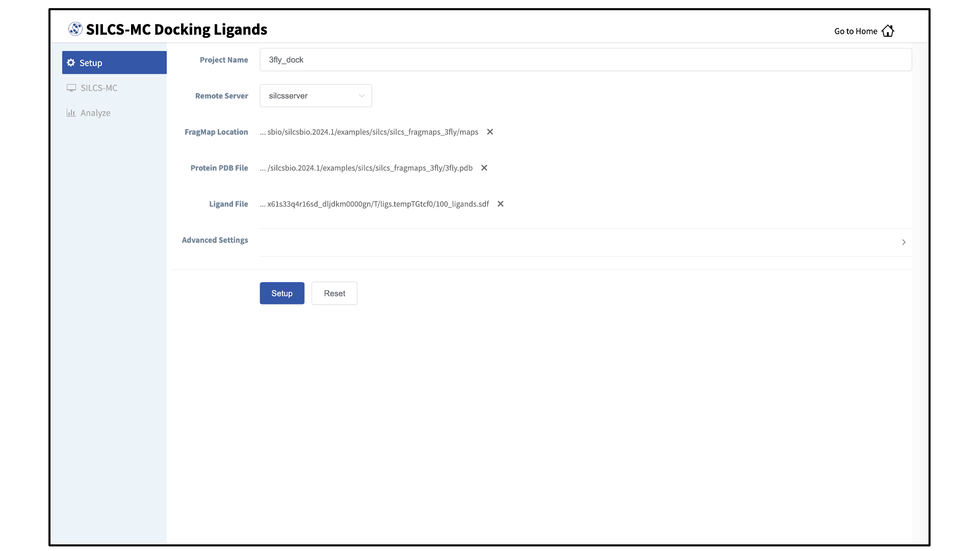
Enter a project name, select the remote server, and input files:
Enter a project name and select the remote server where the SILCS-MC docking jobs will run. Also, provide FragMap and protein input files. You may choose these files from the computer where you are running the SilcsBio GUI (“localhost”) or from any server you have previously configured, as described in File and Directory Selection. You will additionally need to provide a “Ligand SDF File” that contains the database of ligands to be docked. Note that users can modify ligands using the “Modify Ligand” utility available on the “Home Page” (see Modify Ligand for SILCS-MC).
Warning
Ligands in the “Ligand SDF File” must include all hydrogens, including pH-appropriate (de)protonations, and must have reasonable three dimensional conformations.
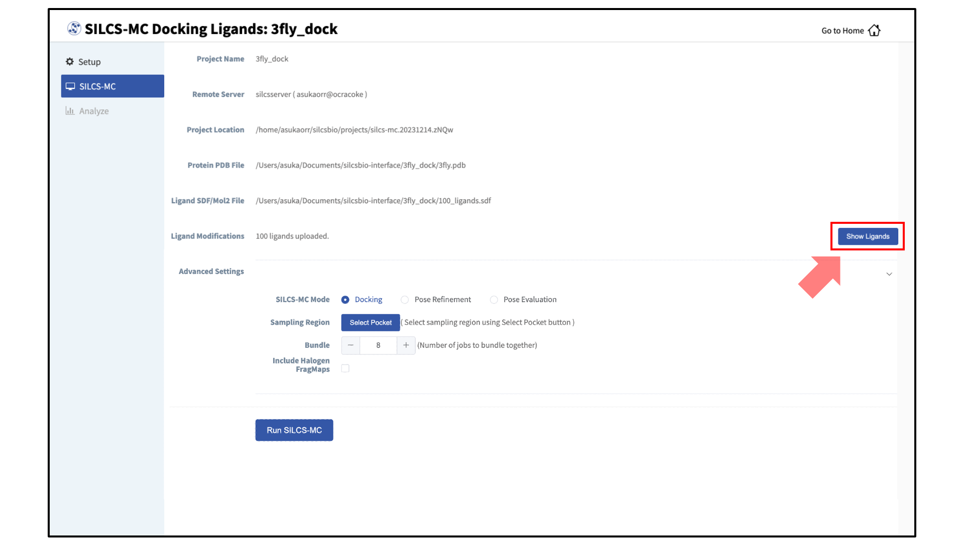
Select the SILCS-MC sampling protocol:
Once all information is entered correctly, press the “Setup” button at the bottom of the page. The page will update to list the number of ligands and show options for the sampling protocol (“Docking”, “Pose Refinement”, or “Pose Evaluation”) and the sampling region. Select the “Docking” option and then press the “Select Pocket” button.
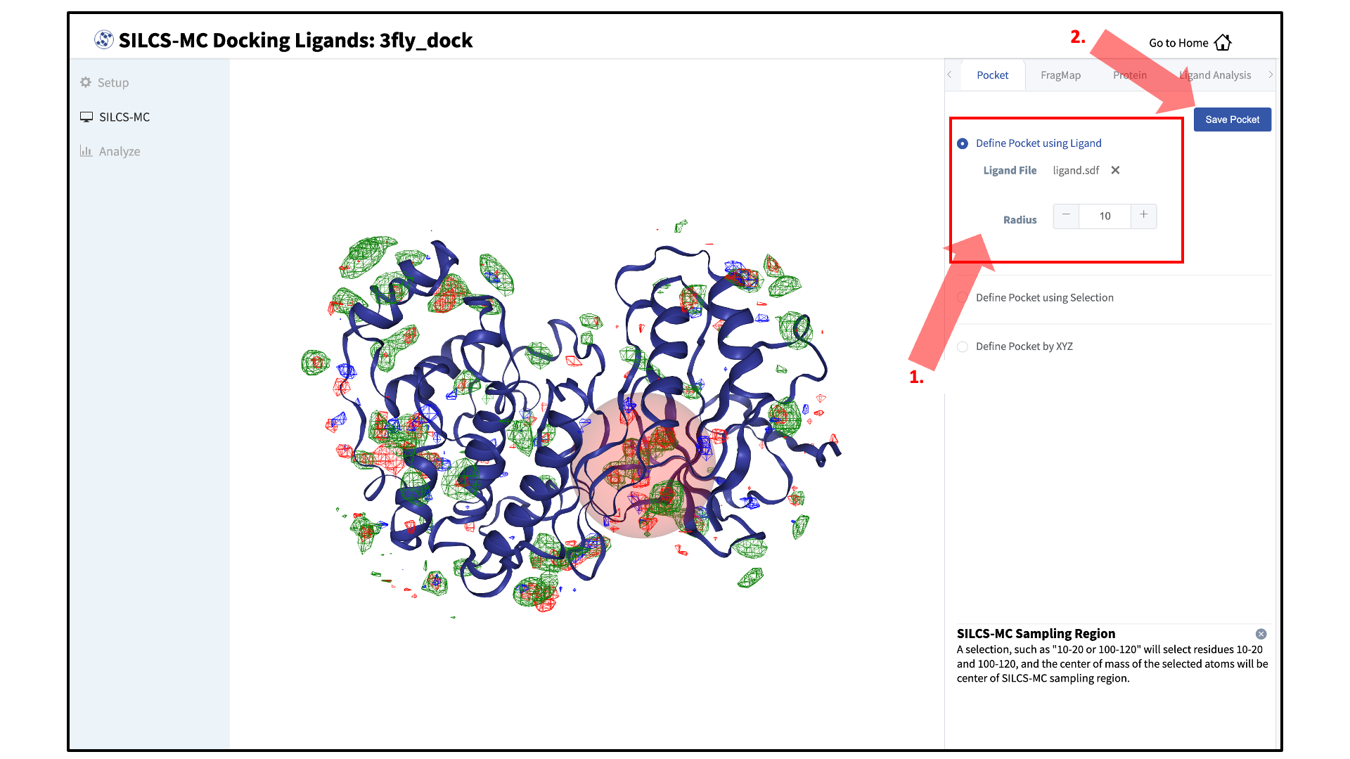
Define a SILCS-MC sampling region:
The GUI will now be showing the protein molecular graphic in the center pane. On the right-hand side in the “Pocket” tab, you can define the pocket center based on the center-of-geometry of a ligand pose (“Define Pocket using Ligand”), or a target residue selection (“Define Pocket using Selection”), or by directly entering an x, y, z coordinate (“Define Pocket by XYZ”). You may also adjust the sampling region’s radius (default value “10” Å) by using the “+/–” buttons. If it is difficult to see the spherical pocket definition in the center panel, hide the protein surface representation. Click on the “Save Pocket” button and the “OK” acknowledgement to continue.
Warning
Adjusting the radius of the spherical pocket may negatively impact the SILCS-MC sampling. Using a radius smaller than the default 10 Å reduces the size of the sampling region, which may disallow the generation of sufficient number of conformations leading to the optimal binding pose being missed. Using a radius larger than the default 10 Å increases the size of the sampling region, thereby increasing the computational cost and time of the SILCS-MC docking runs and increasing the number of irrelevant binding poses.
Launch SILCS-MC jobs:
You will be returned to the previous screen, which now includes “Sampling Region” information consisting of the spherical pocket center and radius.
Tip
If you ran Halogen SILCS simulations for your target, you can include the Halogen SILCS FragMaps in the SILCS-MC posing and scoring by checking the “Include Halogen FragMaps” box.
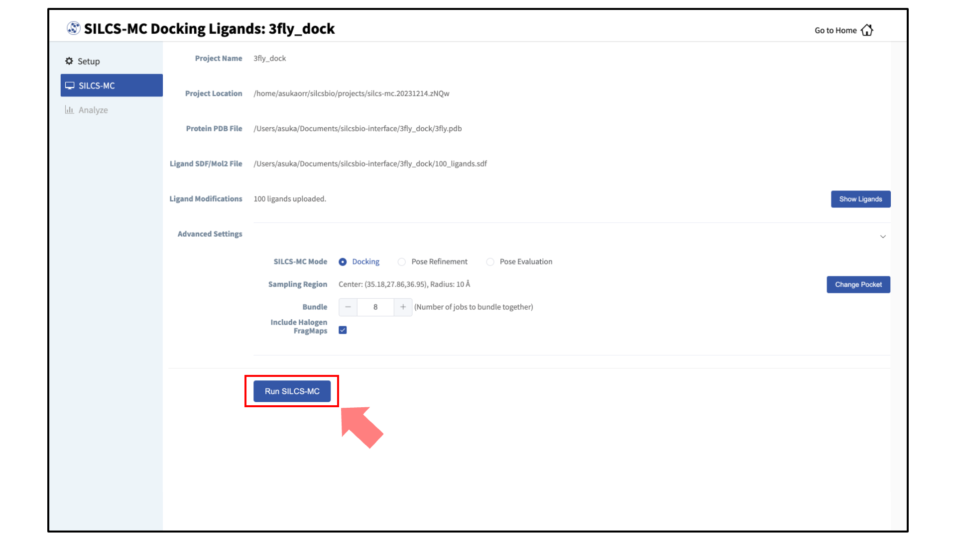
You may now click the “Run SILCS-MC” button to start the SILCS-MC docking. Doing so will submit jobs to the remote server job schedular and list them in a pop-over window.
Once all jobs are submitted, you may click on the “Setup Successful” button to dismiss the pop-over window and return to the previous screen, which will now show a “Simulation Progress” section. You may update this section by scrolling to the bottom of the screen and clicking the “Refresh” button. This will update the progress bars for all of the ligands being docked.
Visualize SILCS-MC docked poses:
Once progress bars for all ligands reach 100%, click on the “Show Chart” button above the “Simulation Progress” section to proceed.
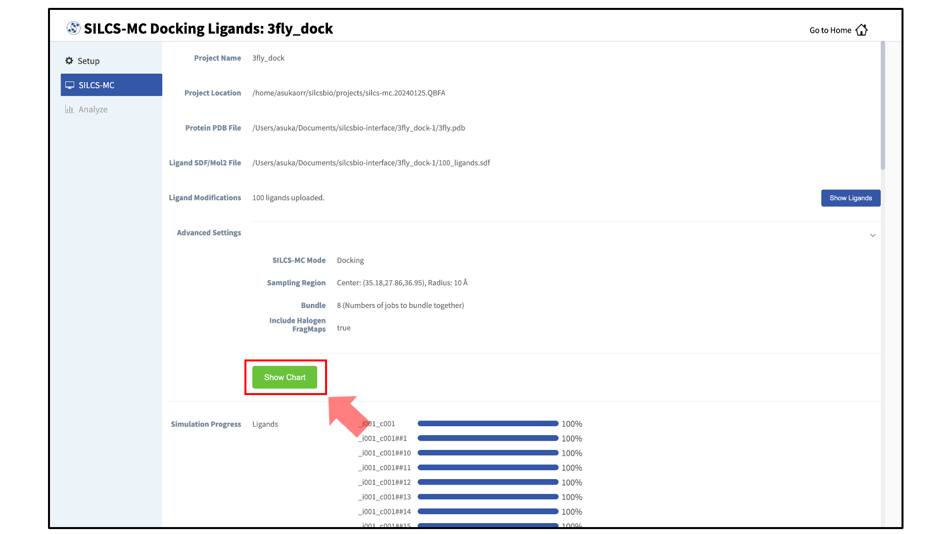
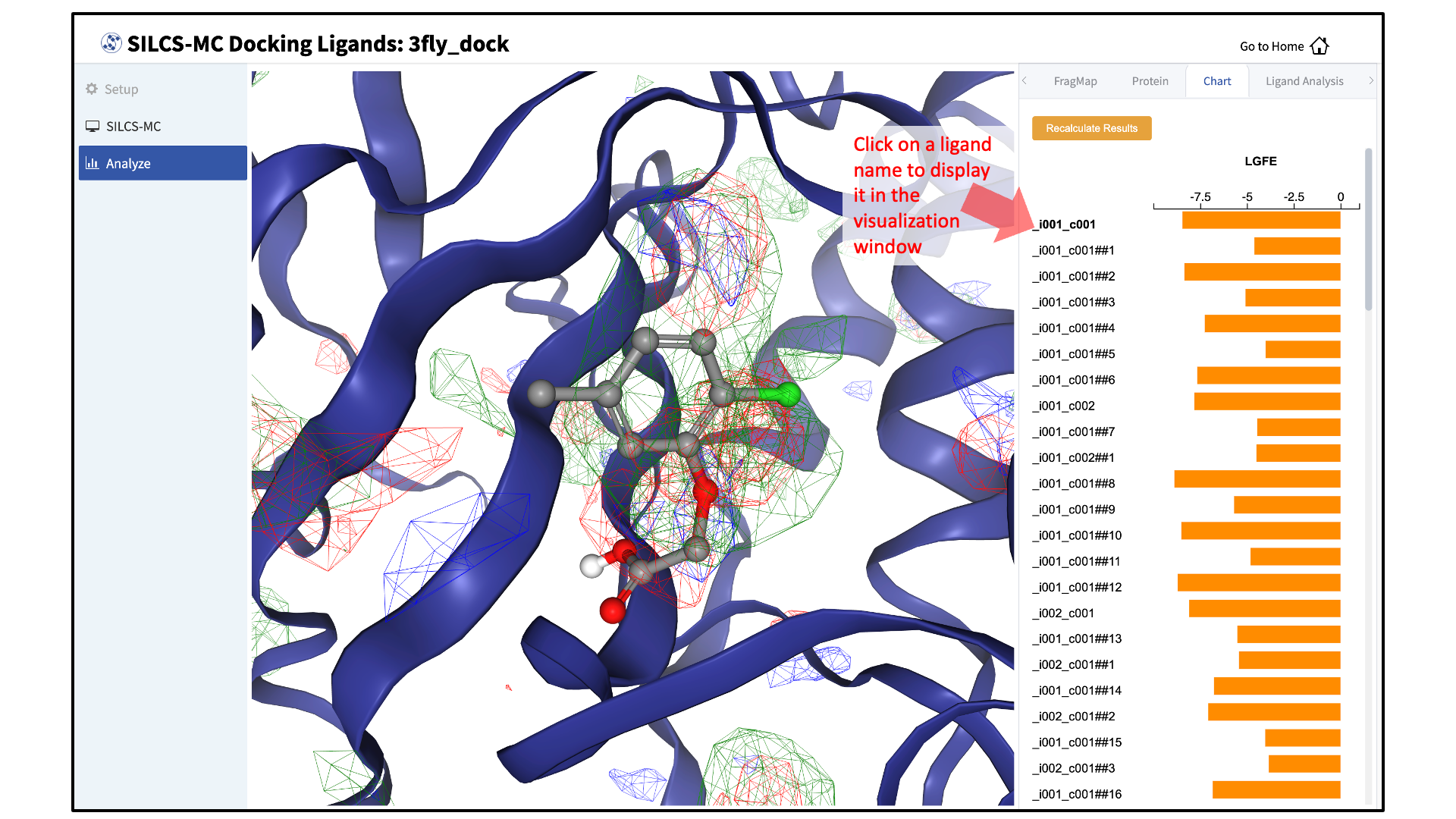
Upon successful completion of this command in the pop-over window, you may click on the green “Data collection finished” button to return to the GUI. A new tab, labeled “Chart” will have been created in the right-hand panel. Under that tab, clicking on a ligand name will display that ligand.
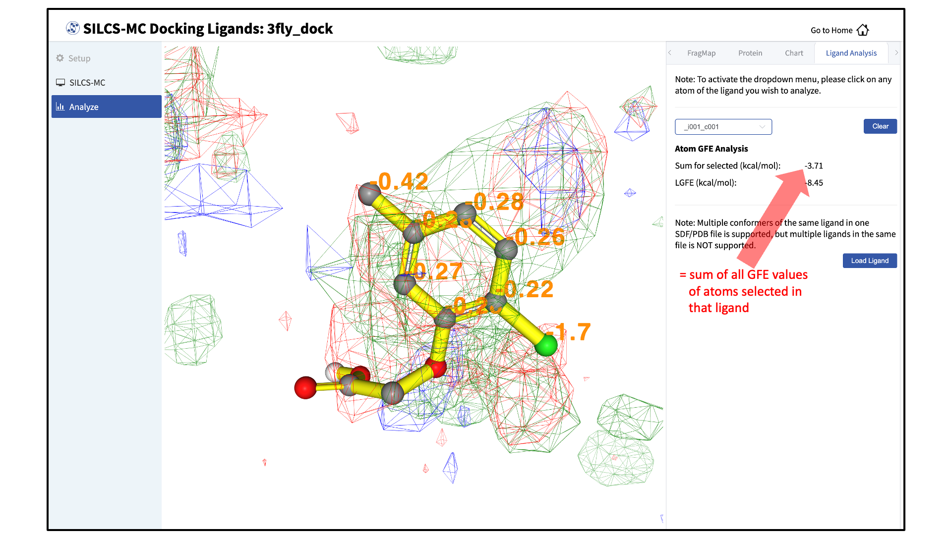
Choosing the “GFE” tab in the right-hand panel will allow you to click on individual atoms within a ligand to see their atomic GFE values. The “GFE” tab will also display the sum of all GFE values of atoms selected in that ligand.
SILCS-MC Docking Using the CLI
Ligands can be docked using SILCS-MC docking through the following steps:
Launch SILCS-MC docking runs:
To set up and run SILCS-MC docking from the command line interface, create a directory containing all the ligands to be evaluated. Each ligand can be stored as a separate SD or Mol2 file. Alternatively, all the ligands can be combined into a single SD file. With this information, enter the following command to set up and launch SILCS-MC docking runs:
${SILCSBIODIR}/silcs-mc/1_run_silcsmc_exhaustive prot=<prot pdb> ligdir=<ligand mol2/sdf directory>Required parameters:
Path and name of protein PDB file:
prot=<protein pdb file>Path and name of directory containing ligand SD or Mol2 files:
ligdir=<ligand directory>If the ligdir option is used, only one molecule per file under
ligdirwill be processed for SILCS-MC docking. For an SD/SDF file containing multiple molecules, usesdfile=<path to sdfile>instead of theligdiroption.Optional parameters:
Path and name of directory containing FragMaps:
mapsdir=<location and name of directory containing FragMaps; default=maps>Name of the directory containing the SILCS-MC output:
silcsmcdir=<name of output directory; default=3_silcsmc>Center of the spherical sampling region:
center=<"x,y,z"; e.g., center="20,30,-2"; default=ligand's center of mass>If the center is not specified by the user, the default center will be calculated from the input ligand’s center of mass, and the initial conformation of the ligand in the SILCS-MC docking runs will correspond to the conformation of the ligand in the input Mol2 or SD file. If the center is specified, then the conformation and orientation of the ligand will be randomized prior to the SILCS-MC docking runs.
Radius of the spherical sampling region:
radius=<radius from center in Å; default=10.0>Path and name of ligand SD file:
sdfile=<location and name of SD file, this option will overwrite ligdir>If the
sdfileoption is used, theligdiroption is not needed and any input for theligdiroption will be overwritten. Thesdfileoption is recommended if the user has an SD file containing all ligands under investigation.Inclusion of halogen FragMaps:
halogen=<true|false; default=false>If halogen FragMaps have been generated (see Setup with halogen probes), they can be included in the SILCS-MC calculation to improve the scoring of halogen-containing compounds. To do so, add the
halogen=trueoption to the1_run_silcsmc_exhaustivecommand.Atom classification scheme:
class=<atom classification scheme (generic or specific); default=generic>Users can use custom atom classification schemes if they wish.
Option to bundle jobs:
bundle=<true|false; default=false>When
bundle=truemultiple (single) jobs will be bundled into a single larger job. The number of jobs to be bundled can be set with thenprocparameter.Number of jobs to bundle (when
bundle=true):nproc=<number of jobs to bundle; default=8>Warning
Ligands, regardless of file format, must include all hydrogens, including pH-appropriate (de)protonations, and must have reasonable three dimensional conformations.
Evaluate docked poses:
The SILCS-MC tool set allows users to easily evaluate docked poses generated from the SILCS-MC docking runs. Users can rank order and collect the docked poses using
2_calc_lgfe_min_avg_sd(see Best-Pose Retrieval) and extract SILCS simulation snapshots in which the protein conformation best complements the docked conformation and orientation of the ligand using3_scan_traj(see Best Protein–Ligand Complex Retrieval).For details on evaluating the resulting SILCS-MC docked poses, please refer to Assessment of SILCS-MC Docked/Refined Poses in CLI.
SILCS-MC Docking Protocol Details
On computers using NVIDIA GPU with CUDA version 11 or later, SILCS-MC Docking spawns
one independent job on one GPU and one CPU per ligand. On computers without NVIDIA GPU,
SILCS-MC Docking spawns five independent single-core serial jobs per ligand.
Each SILCS-MC run involves 1250 cycles (on computers with NVIDIA GPU) or a maximum of 250
cycles and a minimum of 50 cycles
(on computers without NVIDIA GPU) of MC/SA sampling of the ligand within a
defined spherical sampling space.
Each of these cycles,
regardless of GPU or CPU usage, consists of 10,000 steps of MC at a high temperature
followed by 40,000 steps of SA towards a lower temperature. At the beginning of
each cycle, the ligand will be reoriented within the predefined sphere.
The MC sampling has three types of moves: i) molecular translations with a
maximum step size of 1 Å, ii) molecular rotation with a maximum step size of
180 degrees, and iii) intramolecular dihedral rotations with a maximum
step size of 180 degrees. For intramolecular dihedral rotations, only the
rotatable dihedral angles are selected for MC moves. The lowest LGFE scoring
pose from the MC sampling is used as starting pose in the following SA
sampling. The SA sampling also involves the same three types of moves, but
with a smaller step size compared to the MC sampling: i) molecular
translations with a maximum step size of 0.2 Å, ii) molecular rotation with a
maximum step size of 9 degrees and, iii) intramolecular dihedral rotations with
a maximum step size of 9 degrees. The lowest LGFE scoring pose from the SA is
saved in a multi-frame SD file: 3_silcsmc/<run>/out/<lig>.sdf.
On computers using NVIDIA GPU, the MC/SA procedure continues until 1250 cycles have been completed. On computers without GPU, the LGFE score difference between the top three poses (defined by lowest LGFE scores) are evaluated after a minimum of 50 MC/SA cycles. If the LGFE score difference between the are less than 0.5 kcal/mol, then that run is considered converged and terminated. If the top three scored poses are separated by more 0.5 than kcal/mol, the MC/SA procedure continues either until the convergence criterion is met or until a maximum of 250 MC/SA cycles have been completed.
SILCS-MC Pose Refinement
The pose refinement protocol is designed to limit conformational sampling near the ligand input pose supplied by the user. Pose refinement is appropriate when there is high confidence in the input parent ligand pose. The sphere center for the pocket definition is automatically and independently computed for each and every ligand and is the center-of-geometry of that ligand’s input coordinates.
SILCS-MC Pose Refinement Using the SilcsBio GUI
To use SILCS-MC Pose Refinement in the SilcsBio GUI, please see the previous section on
running SILCS-MC docking from the SilcsBio GUI (SILCS-MC Docking Using the SilcsBio GUI); in
Step 3, select the “Pose Refinement” option. Note that there
will be no “Select Pocket” step, as pose refinement assigns the pocket center
based on the center-of-geometry of the input ligand on a per-ligand basis. For multiple
input ligands in a single .sdf file, each ligand will have its own
center-of-geometry used to define the pocket center.
SILCS-MC Pose Refinement Using the CLI
Launch SILCS-MC pose refinement runs:
To set up and run SILCS-MC pose refinement, create a directory containing all the ligands to be evaluated. Each ligand can be stored as a separate
.mol2or.sdffile. Alternatively, all the ligands can be combined into a single.sdffile. With this information, enter the following command to set up and launch SILCS-MC refinement runs:${SILCSBIODIR}/silcs-mc/1_run_silcsmc_local prot=<prot pdb> \ ligdir=<directory containing ligand mol2/sdf> \ mapsdir=<directory containing SILCS FragMaps>
Warning
Ligands, regardless of file format, must include all hydrogens, including pH-appropriate (de)protonations, and must have reasonable three dimensional conformations.
Required parameters:
Path and name of protein PDB file:
prot=<protein pdb file>Path and name of directory containing ligand SD or Mol2 files:
ligdir=<ligand directory>If the ligdir option is used, only one molecule per file under
ligdirwill be processed for SILCS-MC docking. For an SD/SDF file containing multiple molecules, usesdfile=<path to sdfile>instead of theligdiroption.Optional parameters:
Path and name of directory containing FragMaps:
mapsdir=<location and name of directory containing FragMaps; default=maps>Name of the directory containing the SILCS-MC output:
silcsmcdir=<name of output directory; default=3_silcsmc>Path and name of ligand SD file:
sdfile=<location and name of SD file, this option will overwrite ligdir>If the
sdfileoption is used, theligdiroption is not needed and any input for theligdiroption will be overwritten. Thesdfileoption is recommended if the user has an SD file containing all ligands under investigation.Inclusion of halogen FragMaps:
halogen=<true|false; default=false>If halogen FragMaps have been generated (see Setup with halogen probes), they can be included in the SILCS-MC calculation to improve the scoring of halogen-containing compounds. To do so, add the
halogen=trueoption.Atom classification scheme:
class=<atom classification scheme (generic or specific); default=generic>Users can use custom atom classification schemes if they wish.
Option to bundle jobs:
bundle=<true|false; default=false>When
bundle=truemultiple (single) jobs will be bundled into a single larger job. The number of jobs to be bundled can be set with thenprocparameter.Number of jobs to bundle (when
bundle=true):nproc=<number of jobs to bundle; default=8>
Evaluate refined poses:
The SILCS-MC tool set allows users to easily evaluate refined poses generated from the SILCS-MC refinement runs. Users can rank order and collect the resulting poses using
2_calc_lgfe_min_avg_sd(see Best-Pose Retrieval) and extract SILCS simulation snapshots in which the protein conformation best complements the refined conformation and orientation of the ligand using3_scan_traj(see Best Protein–Ligand Complex Retrieval).For details on evaluating the resulting SILCS-MC refined poses, please refer to Assessment of SILCS-MC Docked/Refined Poses in CLI.
SILCS-MC Pose Refinement Protocol Details
On computers using NVIDIA GPU with CUDA version 11 or later, SILCS-MC Pose Refinement
spawns one independent job on one GPU and one CPU per ligand. On computers without
NVIDIA GPU, SILCS-MC Pose Refinement spawns one independent single-core serial jobs
per ligand.
Each SILCS-MC run involves 1250 cycles (on computers with NVIDIA GPU) or 50 cycles
(on computers without NVIDIA GPU) of MC/SA sampling of the ligand within a 1 Å sphere.
The center of the sphere is defined
as the center-of-geometry of the input ligand pose.
Each of these cycles, regardless of GPU or CPU usage,
consists of 100 steps of MC at high temperature followed by 1000 steps
of SA towards a lower temperature. At the beginning of each cycle, the
ligand orientation/conformation will be reset to the one found in the
input file. MC sampling moves are: i) molecular translation with a
maximum step size of 0.5 Å, ii) molecular rotation with a maximum step
size of 15 degrees, and iii) intramolecular dihedral rotation with a
maximum step size of 180 degrees. For intramolecular dihedral rotation,
only the rotatable dihedral angles are selected for MC moves. The lowest
LGFE scoring pose from the MC sampling is used as starting pose in the
following SA sampling. SA sampling moves are smaller than for the MC
phase: i) molecular translation with a maximum step size of 0.2 Å, ii)
molecular rotation with a maximum step size of 9 degrees, iii)
intramolecular dihedral rotation with a maximum step size of 9 degrees.
The lowest LGFE scoring pose from the SA is saved in the multi-frame SD
file 3_silcsmc/<run>/out/<lig>.sdf.
SILCS-MC Pose Evaluation
SILCS-MC pose evaluation allows the user to evaluate the LGFE of an already docked ligand to a target protein for which FragMaps have been pre-computed. The SILCS-MC pose evaluation protocol restricts the conformational sampling of the ligand input pose supplied by the user. Thus the resulting LGFE score corresponds to the ligand binding, in the same input pose, to the target protein.
SILCS-MC Pose Evaluation Using the SilcsBio GUI
To calculate the LGFE of a pose without re-docking or refining the ligand conformation and orientation, please see the previous section on running SILCS-MC docking from the SilcsBio GUI (SILCS-MC Docking Using the SilcsBio GUI); in Step 3, select the “Pose Evaluation” option. Note that there will be no “Select Pocket” step, as pose evaluation will only calculate the LGFE of the input ligand in its original orientation and conformation.
SILCS-MC Pose Evaluation Using the CLI
Launch SILCS-MC pose evaluation runs:
To set up and run SILCS-MC pose evaluation, create a directory containing all the ligands to be evaluated. Each ligand can be stored as a separate
.mol2or.sdffile. Alternatively, all the ligands can be combined into a single.sdffile. With this information, enter the following command to set up and launch SILCS-MC refinement runs:${SILCSBIODIR}/silcs-mc/1_run_silcsmc_fixedpose prot=<prot pdb> \ ligdir=<directory containing ligand mol2/sdf> \ mapsdir=<directory containing SILCS FragMaps>
Warning
Ligands, regardless of file format, must include all hydrogens, including pH-appropriate (de)protonations, and must have reasonable three dimensional conformations.
Required parameters:
Path and name of protein PDB file:
prot=<protein pdb file>Path and name of directory containing ligand SD or Mol2 files:
ligdir=<ligand directory>If the ligdir option is used, only one molecule per file under
ligdirwill be processed for SILCS-MC docking. For an SD/SDF file containing multiple molecules, usesdfile=<path to sdfile>instead of theligdiroption.Optional parameters:
Path and name of directory containing FragMaps:
mapsdir=<location and name of directory containing FragMaps; default=maps>Name of the directory containing the SILCS-MC output:
silcsmcdir=<name of output directory; default=3_silcsmc>Path and name of ligand SD file:
sdfile=<location and name of SD file, this option will overwrite ligdir>If the
sdfileoption is used, theligdiroption is not needed and any input for theligdiroption will be overwritten. Thesdfileoption is recommended if the user has an SD file containing all ligands under investigation.Inclusion of halogen FragMaps:
halogen=<true|false; default=false>If halogen FragMaps have been generated (see Setup with halogen probes), they can be included in the SILCS-MC calculation to improve the scoring of halogen-containing compounds. To do so, add the
halogen=trueoption to the1_run_silcsmc_exhaustivecommand.Atom classification scheme:
class=<atom classification scheme (generic or specific); default=generic>Users can use custom atom classification schemes if they wish.
Option to bundle jobs:
bundle=<true|false; default=false>When
bundle=truemultiple (single) jobs will be bundled into a single, larger job. The number of jobs to be bundled can be set with thenprocparameter.Number of jobs to bundle (when
bundle=true):nproc=<number of jobs to bundle; default=8>
Evaluate poses:
To extract the LGFE scores calculated by SILCS-MC pose evaluation, use
2_calc_lgfe_min_avg_sdfollowing the instructions detailed in Best-Pose Retrieval. Users can additionally extract SILCS simulation snapshots in which the protein conformation best complements the refined conformation and orientation of the ligand using3_scan_traj(see Best Protein–Ligand Complex Retrieval).
SILCS-MC Pose Evaluation Protocol Details
Pose evaluation initiates one single-GPU and single-CPU job (or single-core serial job on computers without NVIDIA GPU or without CUDA version 11 or later) per ligand, and involves a single step evaluation of LGFE. Technically, all step sizes are set to zero and only 1 step of MC and SA is performed in order to get the output LGFE.
SILCS-MC Docking in Slab Mode
For a ligand to reach the active site of a protein, the ligand must diffuse into the active site. Characterizing ligand binding pathways can provide insights into ligand binding/unbinding kinetics and reveal potential protein “gateways” into active sites, which may be targeted for the binding of small molecules to block the active site. The Slab Mode of SILCS-MC docking allows users to dock ligands along a user-defined pathway.
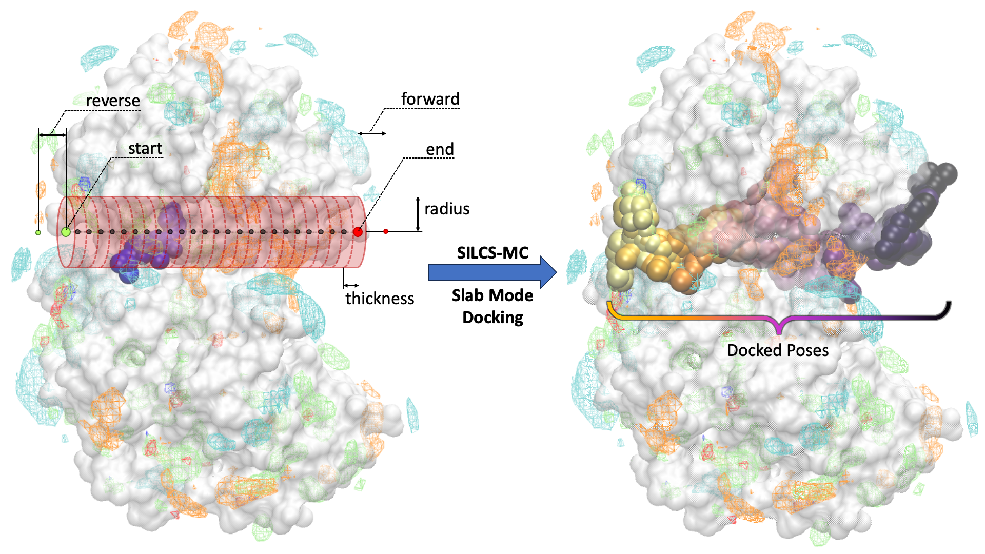
In the Slab Mode of SILCS-MC docking, the user defines the “start” and “end” point (large green and red circles in the figure below, respectively) of a linear pathway for the ligand to be docked along. With the user-defined pathway as the axis, a series of cylindrical sampling regions (red cylinders in the figure below) are constructed with a tunable “radius” and “thickness” spanning the entire length between the start and end point. Users may optionally add additional sampling cylinders beyond the start (“reverse”) and end (“forward”) points (small green and red circles in the figure below, respectively). After running SILCS-MC with Slab Mode, the docked poses of the ligand along the pathway, in sequential order, will be generated (right panel of the figure below).
SILCS-MC Slab Mode Docking Using the CLI
Ligands can be docked along a user-defined pathway using the SILCS-MC Slab Mode docking through the following steps:
Launch SILCS-MC Slab Mode Docking:
To set up and run SILCS-MC docking using the Slab Mode from the command line interface, create a directory containing all the ligands to be evaluated. Each ligand can be stored as a separaate SD of Mol2 file. Alternatively, all the ligands can be combined into a single SD file. Additionally, determine the start and end point, in Cartesian coordinates, of the pathway along which the ligand will be docked. With this information, enter the following command to set up and lauch the Slab Mode SILCS-MC docking run:
$SILCSBIODIR/silcs-mc/1_run_silcsmc_slab prot=<prot pdb> ligdir=<ligand directory> start=<"x,y,z"> end=<"x,y,z">Required parameters:
Path and name of protein PDB file:
prot=<protein pdb file>Path and name of directory containing ligand SD or Mol2 files:
ligdir=<ligand directory>If the ligdir option is used, only one molecule per file under
ligdirwill be processed for SILCS-MC docking. For an SD/SDF file containing multiple molecules, usesdfile=<path to sdfile>instead of theligdiroption.Starting point of the pathway along which the ligand(s) will be docked:
start=<"x,y,z"; e.g., start="20,30,-2">End point of the pathway along which the ligand(s) will be docked:
end=<"x,y,z"; e.g., end="20,30,22">Optional parameters:
Path and name of directory containing FragMaps:
mapsdir=<location and name of directory containing FragMaps; default=maps>Name of the directory containing the SILCS-MC output:
silcsmcdir=<name of output directory; default=3_silcsmc>Increments in which the ligand will be docked along the pathway (thickness of the slab):
thickness=<thickness/height of the slab; default=2.0 A>Sampling radius for each docking run along the pathway (radius of the slab):
radius=<radius of the slab; default=5.0 A>Extension of sampling beyond end point:
forward=<extra slab number of forward sampling after end; default=0>Extension of sampling beyond starting point:
reverse=<extra slab number of reverse sampling before start; default=0>Path and name of ligand SD file:
sdfile=<location and name of SD file, this option will overwrite ligdir>If the
sdfileoption is used, theligdiroption is not needed and any input for theligdiroption will be overwritten. Thesdfileoption is recommended if the user has an SD file containing all ligands under investigation.
Evaluate docked poses:
The SILCS-MC tool set allows users to easily evaluate docked poses generated from the SILCS-MC Slab Mode docking runs. Users can collect the docked poses along the specified pathway using
2_calc_lgfe_min_avg_sdwith theslab=trueparameter (see Best-Pose Retrieval). In addition, using2_calc_lgfe_min_avg_sdwill additionally collect and rank order the resulting docked poses. SILCS simulation snapshots in which the protein conformation best complements the refined conformation and orientation of the ligand using can also be extracted with3_scan_traj(see Best Protein–Ligand Complex Retrieval).For details on evaluating the resulting SILCS-MC Slab Mode docked poses, please refer to Assessment of SILCS-MC Docked/Refined Poses in CLI.
SILCS-MC Slab Mode Docking Protocol Details
SILCS-MC Slab Mode docking spawns a single gpu job per ligand. In SILCS-MC Slab Mode
docking, the pathway along which the ligand(s) will be docked is divided into cylindrical
slabs. By default, the cylindrical slabs are 2 Å thick with a radius of 5 Å. The
thickness and radius of the cylindrical slabs can be customized in the command line
interface (thickness and radius optional parameters; see above). For each
cylindrical slab, a maximum of 250 cycles and a minimum
of 50 cycles of Monte Carlo/Simulated Annealing (MC/SA) sampling of the ligand
within the cylindrical slab is performed. Each of these 250 cycles consists of
10,000 steps of MC at a high temperature followed by 40,000 steps of SA towards a lower
temperature. At the begining of each cycle, the ligand will be reoriented within the
cylindrical slab. The MC sampling has three types of moves: i) molecular translations
with a maximum step size of 1.0 Å, ii) molecular rotations with a maximum step
size of 180.0°, and iii) intramolecular dihedral rotations with a maximum step size
of 180.0°. For intramolecular dihedral rotations, only the rotatable dihedral angles
are selected for MC moves. The lowest LGFE scoring pose from the MC sampling is used
as a starting pose in the folling SA sampling. The SA sampling also involves the
same three types of moves, but with a smaller step size compared to the MC sampling:
i) molecular translations with a maximum step size of 0.2 Å, ii) molecular rotations
with a maximum step size of 9° and, iii) intramolecular dihedral rotations with a
maximum step size of 9°.
For each cylindrical slab, after a minimum of 50 MC/SA cycles, if the LGFE score
difference between the top three poses (defined by lowest LGFE scores) are less than 0.5
kcal/mol, then the run is considered converged and terminated. If the top three scored
poses are separated by more 0.5 than kcal/mol, then the MC/SA procedure continues
either until the convergence criterion is met or until a maximum of 250 MC/SA cycles
have been completed. At the end of all cycles per cylindrical slab, the lowest LGFE
scoring pose for each cylindrical slab is saved and stored in a multi-frame SD file
(3_silcsmc/1/out/<lig>.sdf) with each frame corresponding to the lowest LGFE scoring
pose of a given cylindrical slab along the user-defined pathway.
Assessment of SILCS-MC Docked/Refined Poses in CLI
Upon completion of the SILCS-MC docking and/or refinement simulations, the resulting docked poses can be assessed using tools available with your SilcsBio software. To extract the structures of docked poses and evaluate their LGFE scores (energetic favorability) and 4DBA scores (bioavailability), follow the instructions in Best-Pose Retrieval. To extract protein conformations that complement SILCS-MC docked structures and generate a protein–ligand complex structure, follow the instructions in Best Protein–Ligand Complex Retrieval after extracting the docked poses through Best-Pose Retrieval.
Best-Pose Retrieval
Once the SILCS-MC simulation is finished, users can retrieve the LGFE scores for each ligand subjected to SILCS-MC using the following command:
$SILCSBIODIR/silcs-mc/2_calc_lgfe_min_avg_sd ligdir=<ligand mol2/sdf directory>
The above command will rank order and collect the most energetically favorable (lowest
LGFE) docked poses resulting from the SILCS-MC docking runs. The corresponding
LGFE scores per ligand will be output in the 3_silcsmc/lgfe.csv file (see
below). The most energetically favorable binding pose(s) will be
stored in the 3_silcsmc/minconfpdb/ folder in SD file format.
Below is an example of the contents of the lgfe.csv output from this script:
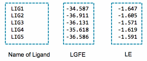
An alternative to the LGFE score is the ligand efficiency (LE). The LE is calculated as the LGFE score divided by the number of heavy atoms in each ligand.
Required parameter:
Path and name of directory containing ligand Mol2/SD files:
ligdir=<ligand mol2/sdf directory>
The same directory containing the ligand Mol2/SD files specified with
ligdirin the previous1_run_silcsmc_exhaustivestep should be used if the poses for all docked ligands are being collected. If only the poses for a subset of the docked ligands is desired, then a new directory containing the Mol2/SD files of the subset of ligands can be specified. Ifsdfilewas used in the previous step, use the samesdfileparameter for this step.
Optional parameters:
Name of the directory containing the SILCS-MC output:
silcsmcdir=<name of output directory; default=3_silcsmc>
The
silcsmcdirshould correspond to thesilcsmcdirspecified in the previous1_run_silcsmc_exhaustivestep. If nosilcsmcdirwas specified in the previous step, then the defaultsilcsmcdir=3_silcsmcshould be used.Path and name of ligand SD file:
sdfile=<location and name of SD file, this option will overwrite ligdir>
The same SD file should be used as in the previous
1_run_silcsmc_exhaustivestep. If thesdfileoption is used, theligdiroption is not needed and any input for theligdiroption will be overwritten. Thesdfileoption is recommended if the user has an SD file containing all ligands under investigation.Number of output poses:
npose=<number of best scoring poses sorted by LGFE; default=1>
By default, only the best scoring, based on LGFE, docked pose will be output. To ouput additional docked poses, use the
nposeparameter and specify the desired number of docked poses. E.g., if 5 poses are desired, usingnpose=5will result in the 5 best scoring poses being output.Option to output docked poses in PDB format:
pdb=<true|false; default=false>
When
pdb=truethe docked poses will be output in PDB format in addition to the default SD file format.Option to output ligand SMILES strings:
smiles=<true|false; default=false>
When
smiles=truethe outputlgfe.csvfile will include the ligand SMILES strings in the second column of the file.Option to extract LGFEs and poses along a pathway for Slab Mode (when
1_run_silcsmc_slabwas used to dock):slab=<true|false; default=false>
When
slab=true, an additional output filelgfe_slab.csvwill be produced. This file will contain the ligand name, step along the pathway (slab), and the ligand LGFE, ligand efficiency (LE), and center-of-geometry at that step. In conjunction withsmiles=true, the ligand SMILES strings will also be output into the second column of thelgfe_slab.csvfile. In addition, an SD file containing the docked poses of the ligand along the user-defined pathway will be stored for each ligand in3_silcsmc/conf_slab/.Option to calculate 4DBA descriptors and 4DBA-LGFE scores:
fourdba=<true|false; default=false>
When
fourdba=truethe four 4DBA descriptors of each input ligand will be calculated and output intolgfe-4dba.csv. A high 4DBA score indicates that the ligand is bioavailable while a low 4DBA score indicates that the ligand is not bioavailable. For more information of 4DBA and LGFE-4DBA scores, please see 4D Bioavailability (4DBA) Calculation.Path to python executable:
python=<path to python executable for 4DBA calculations>
The default python path can be checked using the
which pythoncommand. Therdkit,tqdm,ipythonandscipypackages must be installed for the 4DBA score calculation. Please refer to Python 3 Requirement for more information.
Best Protein–Ligand Complex Retrieval
After retrieving the best ligand pose from SILCS-MC, users can visualize it in the context of SILCS FragMaps. However, since FragMaps are typically visualized with the initial protein structure, the docked ligand pose may overlap with the protein structure. The best protein–ligand complex retrival tool allows users to retrieve simulation snapshots, in which the conformation of the protein (or RNA) best complements the docked ligand, from the SILCS simulations. The most complementary conformations of the protein or RNA are determined by the favorability of non-bonded interactions between the protein/RNA and the docked ligand.
To retrieve complementary conformations of the target protein/RNA, first extract the
protein/RNA trajectory from SILCS simulations by re-running the
silcs/2b_gen_maps step with the option traj=true:
${SILCSBIODIR}/silcs/2b_gen_maps prot=<prot pdb> traj=true
Additionally, use oldversion=true if v2023.1 or older versions was used to
to run 2a_run_gcmd step, i.e., the simulation trajectories were saved without
hydrogen atoms.
The above command will generate traj.xtc and traj.pdb files as output, which will be
used as input for the next step:
${SILCSBIODIR}/silcs-mc/3_scan_traj prot=<prot pdb> ligdir=<ligand SDF/MOL2 directory>
Required parameters:
Path and name of protein PDB file:
prot=<prot pdb>Path and name of directory containing ligand Mol2/SD files:
ligdir=<ligand SDF/MOL2 directory>
Optional parameters:
Name of the output directory:
outputdir=<name of output directory; default=scan_traj>Number of top frames to extract:
top=<number of top frames to extract; default=10>The simulation snapshots are ranked by the interaction energy of the docked pose with the protein conformation extracted from the simulation snapshot. By default only the Lennard-Jones component of the interaction energy is considered, this can be changed using the
sortbyparameter. The lowest interaction energy conformation is considered the most energetically favored conformation and the corresponding frame will be ranked first.Number of frames to skip while processing trajectory:
skip=<number of frames to skip; default=100>Interaction energy component(s) used to rank the frames:
sortby=<type of energy to sort frames by; ELEC/LJ/TOTAL; default=LJ>Users can select from electrostatic (
ELEC), Lennard-Jones (LJ) or total (TOTAL) interaction energies. By default, the simulation snapshots are ranked based onLJ.Option to ignore hydrogen atoms:
noh=<ignore protein hydrogens for energy calculation; true/false; default=false>Users can choose to perform the energy calculation with protein hydrogen atoms ignored. Ligand hydrogen atoms will never be ignored. When
noh=true, this calculation will be performed in addition to the calculation with hydrogens.Path and name of SD file:
sdfile=<location and name of SD file>Only one molecule in each Mol2/SD file under
ligdirwill be processed. If you have SD file with multiple molecules, use thesdfileoption instead of theligdiroption.Warning
The calculation will automatically loop over all ligands in
ligdirorsdfile. If there are many ligands inligdirorsdfile, this calculation may require a long compute time, and ifoldversion=true, many output files may be produced.Number of threads to use:
nproc=<number of threads to use; default=4>Specify calculation for v2023.x or older SilcsBio versions:
oldversion=<true|fase; default=false>Use
oldversion=trueif the option was used to generate traj.xtc/pdb files insilcs/2b_gen_maps. This option should be set totrueif SilcsBio v2023.x or older versions were used to run the SILCS simulations (silcs/2a_run_gcmd).
Tip
For users with access to both the SILCS-Small Molecule Suite and the CGenFF Suite, running standard MD simulation can be helpful to evaluate or refine the protein–ligand complex structure obtained from SILCS-MC Docking or Pose Refinement. The structure retrieved from the process described in Best Protein–Ligand Complex Retrieval may be used to create the initial protein–ligand complex structure for further refinement using MD simulations. For more information on running standard MD simulations through the CGenFF Suite, please refer to Standard Molecular Dynamics (MD) Simulations.
User-Defined Protocols through the CLI
In addition to the default docking, pose refinement, and pose evaluation protocols,
users can define their own SILCS-MC protocols. To do so, copy
${SILCSBIODIR}/templates/silcs-mc/params_custom.tmpl to the location where
you intend to run your custom SILCS-MC protocol. Edit this copy to reflect your
customization; see below for a detailed description of user-definable
parameters. Parameter values in angle brackets in this file, such as
<SILCSBIODIR>, will be replaced automatically at runtime where possible.
After you have edited params_custom.tmpl, use the following command to set
up and run SILCS-MC. Each input ligand can be stored as a separate SD or Mol2
file. Alternatively, all input ligands can be combined in a single SD file.
${SILCSBIODIR}/silcs-mc/1_run_silcsmc_custom prot=<prot pdb> \
    ligdir=<directory containing ligand sdf/mol2> \
    mapsdir=<directory containing SILCS FragMaps> \
    paramsfile=<params_custom.tmpl>
The number of runs that will be spawned can also modified with the command-line
parameter totruns:
${SILCSBIODIR}/silcs-mc/1_run_silcsmc_custom prot=<prot pdb> \
    ligdir=<directory containing ligand sdf/mol2>
    mapsdir=<directory containing SILCS FragMaps>
    paramsfile=<params_custom.tmpl>
    totruns=<# of runs>
Note
.sdf, .sd, or .mol2 files can be placed in the ligdir
directory, and SILCS-MC will read a single molecule from each file.
If a file contains multiple molecules, use of the ligdir
option will result in only the first molecule in the file being processed.
If you have an SD file with multiple molecules in it, replace
ligdir=<directory containing ligand mol2/sdf> with
sdfile=<path to sdfile> to process all molecules in the file.
Warning
Ligands, regardless of file format, must include all hydrogens, including pH-appropriate (de)protonations, and must have reasonable three dimensional conformations.
The full list of user-definable parameters for params_custom.tmpl is:
CGENFF_RULES <cgenff rules_file>(required)This file is needed by the internal CGenFF library to determine the correct force-field parameters for the ligand. The default value is
${SILCSBIODIR}/data/cgenff/cgenff.rulesCGENFF_PAR <cgenff parameter file>(required)Along with the CGENFF_RULES file, this file is needed by the internal CGenFF library to determine the correct force-field parameters for the ligand. The default value is
${SILCSBIODIR}/data/cgenff/par_all36_cgenff.prmSILCS_RULES <silcs rules file>(required)This rules file is used to map the different atoms in the ligand to the corresponding SILCS FragMap types. This mapping is used to determine the appropriate “field” that will be applied to the different atoms in the ligand when attempting an MC-move. The default value is
${SILCSBIODIR}/data/silcs/silcs_classification_rules_2021_generic_apolar_scale_1f.datWhen
silcs_classification_rules_2021_generic_apolar_scale_1f.datis used, ligand atoms are assigned using generic classifications for mapping back to the FragMaps.Additional rules files are available in the
${SILCSBIODIR}/data/silcs/for other mapping schemes, including for more specific classifications and for using halogen FragMaps (see Setup with halogen probes).GFE_CAP <default: 3.0>Maximum allowable unfavorable GFE (kcal/mol) in the MC calculation.
RDIE <default: true>When true, the distance dependent dielectric (RDIE) scheme is used to treat intramolecular electrostatics. When false, CDIE (constant dielectric scheme) is used.
DIELEC_CONST <default: 4>Dielectric constant used in the intramolecular electrostatic interactions calculations.
MINIMIZE_INPUT <default: false>Perform minimization of input structure.
MINIMIZE_BFGS <default: false>Perform minimization of input structure using BFGS algorithm.
MIN_STEPS <default: 10000>Maximum number of steps of minimization performed using the steepest-descent algorithm with the ligand, before initiating MC simulation.
EMTOL <default: 0.01>Minimization is converged when the diff in total energy (totE) across the last 10 steps is smaller than this value. Once this criteria is satisfied minimization terminates.
MC_MOVE_RANGE <default:1.0 180.0 180.0>.Maximum range of translation, rigid body rotation and dihedral rotation per step of MC simulation.
MC_PRNT_FRQ <default: 0>Number of intermediate steps of MC to be written into OUTMCPDBFILE.
MC_STEPS <default: 10000>Number of steps of MC simulation to be performed per cycle.
MC_RUN <default: 1>Number of MC simulation cycles to be performed. By default, SILCS-MC performs one cycle of MC simulation with
MC_STEPS. In some cases, when users want to generate poses and orientations, and then perform a local refinement for each pose, they can setMC_RUNto a higher value.MC_STEPS2 <default: 10000>Number of steps of MC simulation to be performed for later cycle of
MC_RUN, only whenMC_RUNis larger than 1. By default, SILCS-MC performs one cycle (MC_RUN= 1) of MC simulation withMC_STEPS, andMC_STEPS2will be ignored.MC_MOVE_RANGE2 <default:0.1 90.0 60.0>.Maximum range of translation, rigid body rotation and dihedral rotation per step for
MC_STEPS2.SIM_ANNEAL_MOVE_RANGE <default:0.2 9.0 9.0>Maximum range of translation, rigid body rotation and dihedral rotation per step of simulated annealing simulation after MC simulation.
SIM_ANNEAL_STEPS <default: 40000>Number of steps of simulated annealing to be performed per cycle.
INIT_RUNS <default: 50>Number of MC/SA cycles before initiating checks for convergence.
NUM_TOL <default: 3>Number of top-scoring cycles with differences in LGFE less than DELTAE_TOLERANCE, before this simulation (run) is considered converged.
DELTAE_TOLERANCE <default: 0.5>When differences in LGFE of NUM_TOL most-favorable cycles are less than this defined tolerance value, convergence is reached and the program exits
DELTAE_BUFF <default: 10>Progression of MC+SA from one cycle to next is such that LGFE (of lowest conf) from MC should be less than (prev_min+deltae_buff). This ensures that N cycles are proceeding towards a minimum lower than that previously discovered lowest energy conformation.
TOTE_CRITERIA <default: false>When true, instead of LGFE, total energy (totE) of the system is used for convergence checks. Useful when running vacuum-phase MC simulations of the ligand.
TOT_RUNS <default: 250>Maximum number of MC simulation cycles. The program terminates if the
DELTAE_TOLERANCEcriteria is satisfied before reachingTOT_RUNS. Alternately, even if theDELTAE_TOLERANCEcriteria is not satisfied when the number of cycles executed reachesTOT_RUNS, the program terminates.RANDOM_SEED: <default: system-time>Seed used in MC simulation. When not set, system-time is used as a seed.
SIMULATION_CENTER: <x,y,z>Cartesian coordinates of where the MC simulation should be performed.
SIMULATION_RADIUS: <default: 10.0 A>Radius of the sphere within which MC simulation will be performed.
RANDOM_INIT_ORIENT: <true/false>When set to
TRUE,SIMULATION_CENTERshould also be set. The ligand is placed within a sphere of sizeSIMULATION_RADIUSin a random orientation and a random conformation.When set to
FALSE, then the center-of-geometry of the ligand is used as the center for the MC simulation. This is useful when the ligand pose in the pocket is well known.ATOM_TO_RESTRAIN: <atom number in sdf/mol2>When set, a spherical potential is applied to restrain the defined atom within the sphere during MC moves. This enables geometrically restraining a particular pharmacophore feature. Note, when using this feature, supply the full molecule with explicit hydrogens already added. Rrandom pocket pose and placement using
RANDOM_INIT_ORIENTtrue is incompatible with this option.When not set, the entire molecule is free to rotate/move/translate
ATOM_RESTRAINT_CENTER: <x,y,z>To be used in conjunction with
ATOM_TO_RESTRAINoption. This value is used to defined the center of the spherical potential.ATOM_RESTRAINT_RADIUS: <default: 1.0 A>To be used in conjunction with
ATOM_TO_RESTRAINoption. This value is used to defined the radius of the spherical potential. When not defined, then a default of 1 A is used.OUTRMSDFILE <output RMSD file>This file stores the RMSD and LGFE of the lowest energy conformation from each run of the MC/SA simulation. To be used in conjunction with
RANDOM_INIT_ORIENTset totrue.SILCSMAP <MapType> <map name> <scaling factor>(required)Multiple
SILCSMAPentries are typically defined, with each entry pointing to a FragMap filename<map name>.<scaling factor>is used to scale atomic Grid Free Energies (GFEs) for<MapType>atoms in the ligand being scored.<MapType>entries here must correspond to those defined in theSILCS_RULESrules file described above.OUTPUT_FORMAT [SDF|PDB](required)Choice of output format. SDF or PDB is supported.
OUTPUT_FILE <output file name>(required)This file stores the lowest energy conformation from each cycle of the MC/SA simulation.
LOGFILE <output log file>This file stores the energy statistics of the lowest energy conformation from each cycle of the MC/SA simulation.